
| The Evolution of MPL |
Definition of MPLS
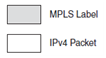
- The MPLS labels are advertised between routers – build a label-to-label mapping.
- These labels are attached to the IP packets (so the routers able to forward the traffic) by looking at the label and not the destination IP address.
- The packets are forwarded by label switching instead of by IP switching.
Benefits of MPLS
- The use of one unified network infrastructure
- Better IP over ATM integration
- Border Gateway Protocol (BGP)-free core
- The peer-to-peer model for MPLS VPN
- Optimal traffic flow
- Traffic engineering
Bogus reason: MPLS not for speed
Peer-to-Peer VPN Model Versus Overlay VPN Model
Overlay VPN model
SP provide a point-to-point links or virtual circuits to the customer
The customer routers will perform routing peering between them and SP never see the customer routes.
Peer-to-peer VPN model
SP will carry the customer data accross the network and perform routing for them (SP’s router directly peering with customer routers at Layer-3).
to privateness or isolation between different customer – use access-list to control data or route-filter
to control routes
MPLS VPN – make peer-to-peer VPN easier
-CE router will peering with PE router at IP Layer.
-to privateness by using concept of VRF(Virtual routing/forwarding) – the data is forwarded in the backbone as labeled packets and ensure the routing info from different customer is kept separate.
1. What are the MPLS applications mentioned in this chapter?
2. Name three advantages of running MPLS in a service provider network.
3. What are the advantages of the MPLS VPN solution for the service provider over all the other VPN solutions?
4. Name the four technologies that can be used to carry IP over ATM.
Multiprotocol Encapsulation over ATM Adaptation Layer 5,
LAN Emulation
Multiprotocol over ATM (MPOA)
5. Name two pre-MPLS protocols that use label switching.
6. What do the ATM switches need to run so that they can operate MPLS?
7. How do you ensure optimal traffic flow between all the customer sites in an ATM or Frame Relay overlay network?
| MPLS Architecture |

The first 20 bits are the label value. This value can be between 0 and 220–1, or 1,048,575. However, the first 16 values are exempted from normal use; that is, they have a special meaning.
The bits 20th to 22nd are the three experimental (EXP) bits. These bits are used solely for quality of service (QoS).
Bit 23rd is the Bottom of Stack (BoS) bit. It is 0, unless this is the bottom label in the stack. If so, the BoS bit is set to 1. The stack is the collection of labels that are found on top of the packet. The stack can consist of just one label, or it might have more. The number of labels (that is, the 32-bit field) that you can find in the stack is limitless, although you should seldom see a stack that consists of four or more labels.
Bits 24th to 31st are the eight bits used for Time To Live (TTL). This TTL has the same function as the TTL found in the IP header. It is simply decreased by 1 at each hop, and its main function is to avoid a packet being stuck in a routing loop. If a routing loop occurs and no TTL is present, the packet loops forever. If the TTL of the label reaches 0, the packet is discarded.
Label Switch Router (LSR) == a router that supports MPLS
Type of LSR
- Ingress LSRs—Ingress LSRs receive a packet that is not labeled yet, insert a label (stack) in front of the packet, and send it on a data link.
- Egress LSRs—Egress LSRs receive labeled packets, remove the label(s), and send them on a data link. Ingress and egress LSRs are edge LSRs.
- Intermediate LSRs—Intermediate LSRs receive an incoming labeled packet, perform an operation on it, switch the packet, and send the packet on the correct data link.
Architecture of LSR
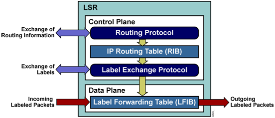
An LSR can do the three operations:
- pop – remove the labels from the top of the label stack before switching the packet out
- push – push the labels onto the received packet
- swap – swap the top label with new label and switched the packet to outgoing data link.
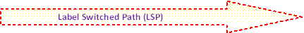
Label Switched Path (LSP) == a sequence of LSRs that switch a labeled packet through an MPLS network or part of an
MPLS network

Forwarding Equivalence Class (FEC)
A group or flow of packets that are forwarded along the same path and are treated the same with regard to the forwarding treatment.
Not all packets that have same label belong to same FEC => because of EXP values might differ; so, ingress LSR will decide which packets belong to which FEC
Ingress router will decide which packet belongs to which FEC based on:
- Packets with Layer 3 destination IP addresses matching a certain prefix
- Multicast packets belonging to a certain group
- Packets with the same forwarding treatment, based on the precedence or IP DiffServ Code Point (DSCP) field
- Layer 2 frames carried across an MPLS network received on one VC or (sub)interface on the ingress LSR and transmitted on one VC or (sub)interface on the egress LSR
- Packets with Layer 3 destination IP addresses that belong to a set of BGP prefixes( BGP routes in the routing table), all with the same BGP next hop == belong to one FEC (all packets that enter MPLS network get a label depending on what the BGP next hop)
Label Distribution
We have 2 ways to distribute the label
-
Piggyback the labels on an existing IP routing protocol/IGP
- a new protocol is not needed to run on the LSRs, but every existing IP routing protocol needs to be extended to carry the labels
- a new protocol is not needed to run on the LSRs, but every existing IP routing protocol needs to be extended to carry the labels
-
Have a separate protocol distribute labels
- being routing protocol independent – whether it is capable of distributing labels or not, a separate protocol distributes the labels and lets the routing protocol distribute the prefixes
If a separate protocol is used to distribute the labels, then let the routing protocol distribute the prefixes. The new protocols are:
- Tag Distribution Protocol (TDP) !is cisco proprietary
- Label Distribution Protocol (LDP)
- Resource Reservation Protocol (RSVP) !is used for MPLS TE only
Label Distribution Protocol / LDP
- For every IGP IP prefix in its IP routing table, each LSR creates a local binding — it binds a label to the IPv4 prefix.
- The LSR then distributes this binding to all its LDP neighbors and become remote bindings.
- The neighbors then store these remote and local bindings in a special table called label information base (LIB).
LDP Hello Message

Note: In Cisco IOS, LDP doesn’t bind labels to BGP IPv4 prefixes.
Label Forwarding Instance Base (LFIB) is the table used to forward labeled packets
- incoming labels – label from the local binding
- outgoing labels – label from the remote binding chosen by the LSR
MPLS Label Spaces
- Per-Interface Label Space – the packet is forwarded base on the incoming interface and the label.
- Per-Platform Label Space –the packet is forwarded base on the label and independently from incoming interface.

The packet is not forwarded solely based on the label, but based on both the incoming interface and the label
- LSR A can advertise label L1 for FEC 1 to LSR B and label L1 for FEC 2 to LSR C
- LSR A can later distinguish from which LSR the packet with label L1 was received.

The packet is forwarded solely based on the label, independently from the incoming interface.
- LSR A distributes FEC 1 with label L1 to LSRs B and C
- When LSR A distributes a label for FEC 2, this label must be a different label than label L1
Note: Cisco IOS, Label Switching Controlled-ATM (LC-ATM) is per-interface label space. All ATM frame-based & non-ATM interfaces have per-platform label space.
Different MPLS Modes when distributing labels on others LSR
- Label distribution mode
- Label retention mode
- LSP control mode
An LSR can use different modes when distributing labels to other LSRs. This section covers three distinct modes, as follows:
- Label distribution mode
- Label retention mode
- LSP control mode
Label Distribution Modes
- Downstream-on-Demand (DoD) label distribution mode
- Each LSR requests its next-hop (that is, downstream) LSR on an LSP, a label binding for that FEC.
- Each LSR receives one binding per FEC only from its downstream LSR on that FEC.
- The downstream LSR is the next-hop router indicated by the IP routing table.
- Unsolicited Downstream (UD) label distribution mode
- Each LSR distributes a binding to its adjacent LSRs, without those LSRs requesting a label.
- An LSR receives a remote label binding from each adjacent LSR.
Label Retention Modes
- Liberal Label Retention (LLR) mode
- LSR keeps all received remote bindings in the LIB.
- The label for the new next-hop router is already in the LIB and the LFIB can be quickly updated with the new outgoing label.
- gives you quicker adaptation to routing changes,
- Conservative Label Retention (CLR) mode
- An LSR that is running this mode does not store all remote bindings in the LIB, but it stores only the remote binding that is associated with the next-hop LSR for a particular FEC.
- Gives you fewer labels to store and a better usage of the available memory on the router.
LSP Control Modes
- Independent LSP Control mode – Cisco IOS
- Each LSR creates a local binding for a particular FEC as soon as it recognizes the FEC.
- The prefix for the FEC is in its routing table.
- Ordered LSP Control mode – ATM switches that running Cisco IOS
- An LSR only creates a local binding for a FEC if it recognizes that it is the egress LSR for the FEC or if the LSR has received a label binding from the next hop for this FEC.
| Label Switching Controlled-ATM (LC-ATM) | ATM frame-based & non-ATM interfaces | |
| MPLS label space | per-interface label space | a per-platform label space |
| Label Distribution mode | Downstream-on-Demand | Unsolicited Downstream |
| Label Retention modes | Conservative Label Retention (CLR) | Liberal Label Retention (CLR) |
1. Name the four fields that are part of a label.
2. How many labels can reside in a label stack?
3. In which layer does MPLS fit in the OSI reference model? Layer 2.5
4. Which table does an LSR use to forward labeled packets?
5. What type of interfaces in Cisco IOS uses the Downstream-on-Demand label distribution mode and the per-interface label space?
6. Why does the MPLS label have a TTL field?
| Forwarding Labeled Packets |
There is 3 operation
- SWAP – the top label of incoming packet is swapping with a new label.
- PUSH –one label is added on top of the swapped label.
- POP –the top label is removed.
- Untagged/No Label –the label stack is removed ad forwarded as normal packet.
- Aggregate – the label stack is removed and an IP lookup is done on the IP packet(looking in CEF table).
NOTE: The LSR sees the 20-bit field in the top label, looks up this value in the LFIB, and tries to match it with a value in the local labels list.
IP Lookup (CEF) vs Label Lookup (LFIB)
When a router receives an IP packet, the IP lookup is done in the CEF Table. When a router receives a labeled packet, the label lookup is done in the LFIB of the router. The router knows that it receives a labeled packet or an IP packet by looking at the protocol field in the Layer 2 header.

IP-to-IP
IP-to-Label – LSR receives an IP packet and forwards it as labeled
Label-to-IP – LSR receives a labeled packet then strip off the labels and forward it as an IP packet
Label-to-Label – LSR receives a labeled packet then strip off the labels and forward is as a labeled packet


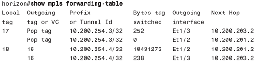
LSR received a packet with top label 16; it removes all labels then forwards it as IP packet. The “Untagged” means all labels removed and the packet forwarded as normal IP packet.
LSR receive a packet with top label 18, it removes the top label and pop one label then forwards as label packet or IP packets
LSR receive a packet with top label 22 -> swap with label 17 then forward it to eth0/0/0 interface Label-to-label forwarding

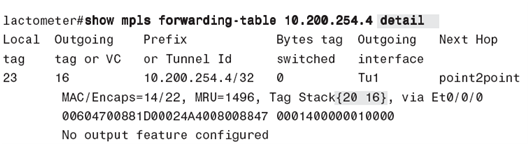
LSR receive a packet with top label 23, it is swapped the label with label 20 and label 16 is pushed onto label 20.

The outgoing label in the LFIB shows “Aggregate” – LSR can’t forward this packet with label-swapping the top label and LSR need to remove the label and must do an IP lookup for forwarding this packet.
Load Balancing Labeled Packets

If labeled packets are load balance – they can have same outgoing label or different label
>> Same label if 2 links are between a pair of routers & belong to the platform label space.
>> Different label if multiple next-hop LSR exist because next-hop LSRs assign labels independently.
Reserved Labels
Labels 0 through 15 are reserved labels and not been used for the normal case.
Label 0 is the explicit NULL label
Label 1 is the router alert label
Label 2 is the explicit NULL label for IPv6
Label 3 is the implicit NULL label
Label 14 is the OAM alert label.
The other reserved labels have not been assigned yet.
Label 0 of explicit NULL
The implicit NULL has one downside: The packet is forwarded with one label less than it was received by the penultimate LSR (a top label pop off). Inside the pop off label, the label also holds the Experimental (EXP) bits. When a label is removed, the EXP bits are also removed and EXP is used for QoS and the QoS operations cannot be performed.
The explicit NULL label is the solution. Because the egress LSR signals the IPv4 explicit NULL label (label 0) to the penultimate hop router. The egress LSR then receives labeled packets with a label of value 0 as the top label. The LSR cannot forward the packet by looking up the value 0 in the LFIB because it can be assigned to multiple FECs. The LSR just removes the explicit NULL label. After the LSR removes the explicit NULL label, another lookup has to occur, but the advantage is that the router can derive the QoS information of the received packet by looking at the EXP bits of the explicit NULL label.
Label 1 == Router Alert option
When the Router Alert label is the top label, it alerts the LSR that the packet needs a closer look. Therefore, the packet is not forwarded in hardware, but it is looked at by a software process. When the packet is forwarded, the label 1 is removed. Then a lookup of the next label in the label stack is performed in the LFIB to decide where the packet needs to be switched to. Next, a label action (pop, swap, push) is performed; the label 1 is pushed back on top of the label stack.
(Detail in MPLS operation and maintenance)
Label 3 == implicit NULL
In Cisco IOS—assigns the implicit NULL label to its connected and summarized prefixes. The benefit of this is that if the egress (end router) LSR were to assign a label for these FECs, it would receive the packets with one label on top of it. (Pop 1 label).
The egress LSR signals the connected LSR (or penultimate /PHP router) in the LSP to send the packets without a label. The egress LSR signals the penultimate LSR (LSR connected to egress LSR) to use implicit NULL by sending a label 3. The result is that the egress LSR will be pop top label. In this case, egress LSR receives an IP packet and needs to perform an IP lookup to be able to forward the packet. (Normally used in MPLS VPN operation).
NOTE:
PHP is the default mode in Cisco IOS. In the case of IPv4-over-MPLS, Cisco IOS only advertises the implicit NULL label for directly connected routes and summarized routes.
Although the label 3 signals the use of the implicit NULL label, the label 3 will never be seen as a label in the label stack of an MPLS packet. That is why it is called the implicit NULL label

Label 14 / OAM alert (Operation and Maintenance alert)
- Basically used for failure detection, localization & performance monitoring.
- Cisco IOS doesn’t use label 14 but just performs MPLS OAM.
The normal labels value
The label value is 20 bits (220) and the labels used for normal forwarding are from 16 to 220.
Cisco IOS default range: 16 to 100,000 for IGP but BGP is insufficient and need to change to max using a command.
# mpls label range 16 1048575
Time To Live behavior
TTL = 255 and decremented by 1 at each hop.
If TTL = 0, router send ICMP message type 11, code 0 = time exceeded to the originator of IP packet.
TTL behavior in MPLS
IP packet enter MPLS cloud, ingress LSR
copy IP TTL into MPLS TTL after being decremented by 1. At egress LSR, copy back the IP TTL from MPLS TTL after decremented by 1. In Cisco IOS by default is not copy the value, if MPLS TTL is greater than IP TTL of the received labeled packets.
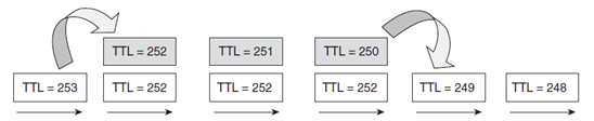
TTL behavior for Label-to-Label operation
Swap – the TTL of incoming label -1 is copied to the swapped label. (If TTL=243, after swapping TTL=242)
Push – the TTL of the top label –1 is copied to the pushed labels. (if TTL top label =242, the pushed TTL=241)
Pop – the TTL of the top label –1 is copied to 2nd top label before top label pop off. If TTL top label greater than 2nd top label, copy doesn’t not happen.
TTL expiration
When a labeled packet is received with a TTL of 1, the receiving LSR drops the packet and sends an ICMP message “time exceeded” (type 11, code 0) to the originator of the IP packet. However, the ICMP message is not immediately sent back to the originator of the packet because an LSR might not have an IP path toward the source of the packet. The ICMP message is forwarded along the LSP the original packet.

Important to P router, where TTL expires, what is the MPLS payload is.
- If IPv4 or IPv6 packets, IOS can generate the ICMP “time exceed” message and forward it along the LSP path.
- If packet is not IPv4/v6, (in case of AToM packet) P router can’t generate the messages because AToM is layer 2 frame because lookup is not possible and P will drop the packet.
MPLS MTU
Max Transmit Unit
MPLS MRU (Maximum Receive Unit)
- Parameter Cisco IOS uses
- MRU informs the LSR how big a received labeled packet of a certain FEC can be forwarded out of this LSR without fragmenting it. This value is actually a value per FEC (or prefix) and not just per interface. The reason is that labels can be added to or removed from a packet on an LSR.
Fragmentation of MPLS Packets
If an LSR receives a labeled packet that is too big to be sent out on a data link, the packet should be fragmented. The LSR strips off the label stack, fragments the IP packet, puts the label stack (after the pop, swap, or push operation) onto all fragments, and forwards the fragments.
If the IP packet has the Don’t Fragment (DF) bit set, the LSR cannot fragment the IP packet, but drops the packet and returns an ICMP error message “Fragmentation needed and do not fragment bit set” (ICMP type 3, code 4) to the originator of the IP packet.
If IP packets are fragmented can cause the performance impact, Path MTU Discovery method should use to avoid this.
Path MTU Discovery
- Most modern IP hosts are able to reduce size of MTU automatically.
- If a router can’t forward the packet without fragmenting it but notice of DF (don’t fragment) bit is set, then router will drop that packet.
- Router sends an ICMP error message “fragmentation need and DF bit is set” (type 3 code 4) to the host.
- The host will reduce the MTU size automatically.
1. What does the push operation do on a labeled packet?
2. Which Cisco IOS command do you use to see what the swapped label is and which labels are pushed onto a received packet for a certain prefix?
3. What does the outgoing label entry of “Aggregate” in the LFIB of a Cisco IOS LSR mean?
4. What label value signals the penultimate LSR to use penultimate hop popping (PHP)?
5. What are the value and the function of the Router Alert label?
6. Why does an LSR forward the ICMP message “time exceeded” along the LSP of the original packet with the TTL expiring instead of returning it directly?
7. Is using Path MTU Discovery a guarantee that there will be no MTU problems in the MPLS network?
8. Why is MTU or MRU such an important parameter in MPLS networks?
| Label Distribution Protocol |
Story of LDP
The labels can be distributed in two ways: piggyback the labels on an existing routing protocol, or develop a new protocol to do just that.
If a new protocol created from the ground up, we must make it routing independent and able to work with any IGP. That is exactly the reason why LDP was created. It carries the label bindings for the FECs in the MPLS network.
LDP overview
- To get packet across a label switched path (LSP) through MPLS cloud, all LSR must run LDP to exchange label binding.
- LFIB (Label Forwarding Info. Base)– the table that forwards labeled packets
-
LDP has 4 major functions:
- The discovery of LSR that are running LDP
- Session establishment and maintenance
- Advertising of label mapping
- Housekeeping by means of notification.
The discovery of LSR
-
LSRs that are running LDP send LDP Hello messages on all links that are LDP enabled.
- # ip cef
- # mpls ip
- # ip cef
-
LDP Hello Messages
use UDP/646 and multicast to group 224.0.0.2 multicast address. The LSR that received this LDP Hello message on one of it interface is being aware of the presence of LDP router. The Hello Message contains of- Hello interval – 5 sec
- Hold time – 15 sec
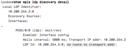
- # show mpls ldp discovery detail !checking discovered LDP neighbors.
- # show mpls interfaces !quickly check interface running LDP
-
LSR that is running LDP has an LDP ID (6-bytes= 4-byte for identifying LSR + 2-bytes for identifying the label space)
- 4-bytes are for the highest IP address from an interface or IP loopback.
-
Change LDP ID
- # mpls ldp router-id <interface> force
- # mpls ldp router-id <interface> force
-
2-bytes – if ‘0’ label space areper-platform

 – if non-zero, label space is per-interface (is used for LC-ATM links)

- MPLS LDP router ID need to be present in the routing table. If NOT, LDP session is not formed.
-
If the IP address with “no route” in the routing table, LDP session is not established.
- # show mpls ldp discovery [detail]
- # show mpls ldp discovery [detail]
LDP session Establishment and Maintenance
-
To establish session, use TCP/646 with other LSR and both LSRs negotiate LDP session parameters.
- Timer values
- Label distribution method
- Virtual path identifier(VPI) or virtual channel identifier (VCI) for Label Controlled ATM (LC-ATM)
- Data-Link Connection Identifier (DLCI) ranges for LC-Frame Relay.
-
After session is UP, maintain by LDP packets or periodic keepalive message.
- Each time receive this packet, the keepalive timer/hold timer is reset for that peer.
- Default is 180 sec (keepalive/Hold time)
- Keepalive interval(KA) is 60 sec (frequently)
-
If two SLR routers have 2 or more links connected together, instead of using IP address to establish the session, we can specify an loopback interface to establish session.
- # mpls ldp discovery transport-address <interfaceIP | lo0>
- # mpls ldp discovery transport-address <interfaceIP | lo0>
-
Number of LDP sessions
-
Per-platform label space
- 1 session is enough because all label binding is same label space and one label space per-session.
- Used by frame-mode interface links
-
Per-interface label space
- Each label binding has relevance only to that interfaces and can’t be shared. If 4 label binding for each interface, 4 session need.
- LC-ATM links requires its own LDP session to exchange labes.
-


Frame is per-platform label space, 1 session is enough.
LC-ATM is per-interface label space, 3 sessions are needed.
Advertising of Label Mappings/label bindings
- Advertising label bindings is the main purpose of LDP.
-
There are 3 modes which LSRs can be:
-
Advertisement
- Unsolicited Downstream (UD) vs Downstream-on-Demand (DoD)
-
Label retention
- Liberal Label Retention (LLR) vs Conservative Label Retention (CLR) mode
-
LSP control mode
- Independent LSP Control vs Ordered LSP Control mode
-
Label withdrawing
When an LDP peer advertises a label binding, the receiving LDP peers keep it until the LDP session goes down or until the label is withdrawn. The label might be withdrawn if the local label changes(if the interface with a certain prefix on it goes down).
Housekeeping by means of Notification
- Notification messages are needed for the housekeeping of LDP sessions. The notification messages signal significant events to the LDP peer. These events might be Error Notifications or Advisory Notifications.
- If an Error Notification occurs, the sending LSR and receiving LSR should terminate the LDP session immediately.
- Advisory Notifications are used to send information about the LDP session or a message received from the peer
-
The events that signaled by sending notification messages:
- Malformed protocol data unit (PDU) or message
- Unknown or malformed type-length-value (TLV)
- Session keepalive timer expiration
- Unilateral session shutdown.
- Initialization messages events
- Events resulting from other messages
- Internal errors
- Loop detection
- Miscellaneous events.
Targeted session
Normally, LDP sessions are set up between directly connected LSRs. Targeted LDP session is an LDP session between LSRs that are not directly connected. Examples of LDP session is needed are AToM networks and TE tunnels in an MPLS VPN network
AToM; an LDP session must exist between each pair of PE routers. The remote LDP session is set up when configuring the #xconnect command on the PE routers of the AToM network.
TE tunnel; with the TE tunnels ending on a P router, the head-end and the tail-end LSR of the TE tunnel need a targeted LDP session between them to get the MPLS VPN traffic correctly label-switched through the MPLS VPN network.
!
mpls ldp neighbor [vrf NAME] IP-TARGET [ldp | tdp]
!
Note: the [vrf NAME] is referring to Carrier’s Carrier (CsC) scenario which LDP need to be established between VRF interfaces.
Advantage;
Improve the label convergence time compared to the convergence time with directly connected LDP peers when there are flapping links. That is because when the link between two LSRs goes down, the LDP session is lost. With a targeted LDP session and an alternative path to get the LDP TCP packets from one LSR to the other, the LDP session stays up when the link between the two LSRs goes down

New-york and Sydney are not directly connected but want both routers to have LDP session – configure both as targeted.
Another way is configure one router as targeted LDP neighbor and the other on as to accept targeted LDP sessions from specific LDP routers.

LDP Authentication
- LDP sessions are TCP session – can be attacked by spoofed TCP segments.
- To protect – MD5 authentication (password) and the password never be transferred.
# mpls ldp neighbor [vrf VPN-NAME] IP-NEIGHBOR password [0-7] PASSWORD-STRING
- If one side is configured and another side is not, following message is logged.
- If password is not match, following message is logged.

Controlling the Advertisement of Labels via LDP
We can control the advertisement of labels. Configured LSR to advertise or not certain labels to certain LSR peers then use the locally assigned labels as outgoing label on those LSRs.
# mpls ldp advertise-label [vrf NAME] [interface NAME |for PREFIX-ACL] to PEER-ACL]]
In the case of MPLS VPN, the important prefixes to get the customer VPN traffic through the MPLS network are the BGP next-hop prefixes, which are usually the loopback interfaces on the PE routers. We can choose not to advertise the label bindings for the prefixes belonging to the other interfaces on the PE or P routers.
In case of LC-ATM, we cannot control LDP advertisement using this command because LC-ATM network use DoD as advertisement mode. The command # mpls ldp request-labels
is used instead of the command above.


There is only 10.200.254.3/32 and 10.200.254.4/32 are advertised to LDP peer 10.200.254.5 (madrid)


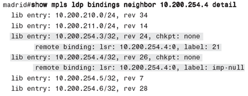
The other prefixes advertised from router Sydney to the router Madrid have no more remote binding.

In the LFIB of router Madrid, only 2 prefixes (10.200.254.3/32 & 10.200.254.4/32 have a valid outgoing label and the others have “No Label”
MPLS LDP inbound Label Binding Filtering
- Filter out incoming label binding from an LSR neighbor
# mpls ldp neighbor [vrf NAME] IP-NBR labels accept ACL

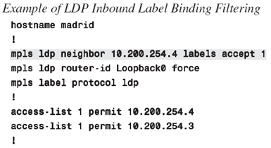
The configuration shows it limits the accepted label binding to10.200.254.3/32 and 10.200.254.4/32 only
LDP Autoconfiguration
- LDP is enabled on an interface by command # mpls ip.
- LDP usually enabled on all interfaces separately by enabling LDP auto-configuration for the IGP. So, every interface which IGP is running has LDP enabled.
!
router ospf 10
mpls ldp autoconfig area 0
!
- Disable LDP on specific interface.
# no mpls ld igp autoconfig
Interface config => LDP is enabled through interface # mpls ip command.
IGP config => LDP is enabled through the router # mpls ldp autoconfig command.
MPLS LDP-IGP Synchronization Configuration
Problem:
A common problem with MPLS networks running LDP is that when the LDP session is broken on a link, the IGP still has that link as outgoing; thus, packets are still forwarded out of that link because of LDP and IGP are not synchronized each other.
If IPv4-over-MPLS, not an issue because if LDP broken, the packet become unlabeled but still can be forwarded as IPv4 packets until they become labeled again on next LSR.
However, in MPLS VPN, the packets are IPv4 packets, but forwarding based on VRF routing table. This table is private for one customer and is present only on the edge LSRs or PE routers. Therefore, when the MPLS VPN packets become unlabeled on the core LSRs (P routers), they are dropped.
If one LDP session being DOWN while the IGP adjacency is UP, between 2 LSRs can result a major problems because much traffic can be lost.
Solution:
MPLS LDP-IGP synchronization – this feature ensures that link is not used of forward traffic when LDP session across the link is down but forwarded to another links.
How it works?
When activated on an interface, the IGP announces that link with maximum metric until the synchronization is achieved, or until the LDP session is established on that interface. The maximum link metric for OSPF is 65536 (hex 0xFFFF).
After that label bindings have been exchanged, the IGP advertises the link with its normal IGP metric. Basically, OSPF does not form an adjacency across a link if the LDP session is not established first across that link.
In some cases, it might not be desirable to keep waiting for the IGP adjacency to be established. So, we configured a Holddown timer for synchronization. If the timer is expires before the LDP session is established, the OSPF adjacency is built.
Configuration:
!
router ospf 10
mpls ldp sync ! # no mpls ldp igp sync to disable it
!
By default, if synchronization is not achieved, the IGP waits indefinitely to bring up the adjacency. Globally command,
# mpls ldp igp sync holddown <msecs>
The command will instruct the IGP to wait, and then after the synchronization Holddown timer expires, the IGP forms an adjacency across the link. As long as the IGP adjacency is up, while the LDP session is not synchronized, the IGP advertises the link with maximum metric. So the interface is no t used to forward traffic unless it is only path out of the LSR.
# debug mpls ldp sync [interface NAME]
MPLS LDP Session Protection
Problem:
- If a link is flapping – session will be disrupted.
- The impact is the routing protocol and LDP can take time to rebuild the neighbor ship. LDP has to rebuild the LDP session and must exchange the label bindings again.
Solution:
- When connected links is down, the targeted LDP session is kept UP as long as an alternative path exists.
- The LDP link adjacency is removed when link down but the targeted adjacency keeps the LDP session UP – after the links is UP, LSR doesn’t need to re-establish the LDP session.
- The command is: # mpls ldp session protection [vrf NAME] for ACL duration SECONDS
-
We need to enable on both LSR. If cannot, enable it on one side, the another side LSR need to accept the targeted LDP Hellos by configuring
# mpls ldp discovery targeted-hello accept
LDP Graceful Restart
A mechanism for LDP peers to preserve the MPLS forwarding state when the LDP session goes down. As such, traffic can continue to be forwarded without interruption, even when the LDP session restarts.
1. What is the fundamental purpose of LDP?
2. Name the four main functions that LDP takes care of.
3. How can you reduce the number of label bindings on an LSR?
4. What problem does MPLS LDP-IGP synchronization solve?
5. How many LDP sessions are established between two LSRs that have six links between them, of which two links are LC-ATM links and four are frame links?
6. What do you need to configure to protect the LDP sessions against attacks?
7. What trick does MPLS LDP-IGP Synchronization employ to ensure that the link is not used to forward traffic while the LDP session is unsynchronized?
8. What does LDP Session Protection use to protect an LDP session?
- d Bit Rate (Multi-VC TBR) was explained as a feature that can provide Cos for LVC.
